Ignition System
The ignition timing is set at the factory and is not adjustable. To troubleshoot the ignition system, you will need a digital multimeter. Perform the following checks. Before performing any tests make sure the electrical connections are not loose or corroded. Also, make sure the engine has good compression, the transmission is in neutral, The engine kill switch is in the run position, the main fuse is not blown, and the battery has a full charge.
SAFETY FIRST: Protective gloves and eyewear are recommended at this point.
Spark Check
Caution: Do not touch the spark plug or spark plug wire while cranking or running the engine as this can result in a severe shock.
Check the spark plug to see if it is the correct type and gapped properly. If the spark plug is black and fouled, replace it. See the Spark Plug topic for more information.
Disconnect the spark plug caps from the spark plugs. Check the spark plugs for spark one at a time.
Connect a known good spark plug to the cap and ground the plug to the frame. Push the engine start button and check that the plug will spark. Repeat the process with the other spark plugs. If the plug does not spark go through the following procedures to find the problem.
Ignition Coils
Removal
Remove the fuel tank. See the Fuel Tank topic for more information.
Remove the spark plug caps from the spark plugs. See the Spark Plugs topic for more information.
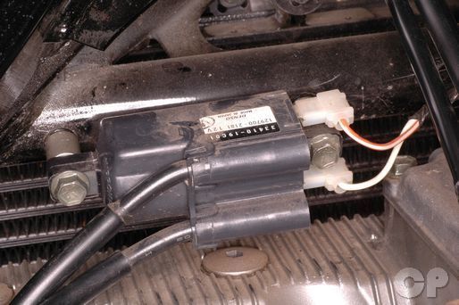


Loosen the ignition coil mounting bolts with a 10 mm socket. There are two mounting bolts for each coil.


Remove the ignition coils from the frame.


Remove the leads from the ignition coil terminals.


Free the spark plug wires from the stay. Remove the ignition coils and spark plug wires from the engine.
Resistance
| Ignition coil resistance | Primary ~ 2-4 Ω |
| Secondary ~ 30-40 kΩ (600 1988 - 1989, 1991 - 1997) |
|
| Secondary ~ 12-18 kΩ (600 1990) | |
| Secondary ~ 12-18 kΩ (750) |
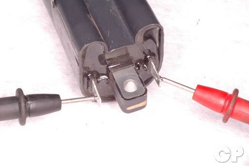
Inspect the ignition coil primary resistance between the lead terminals.
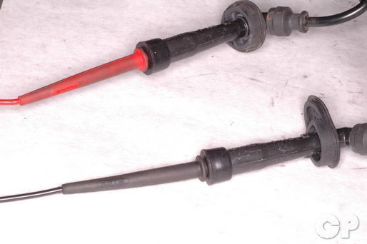
Inspect the ignition coil secondary resistance between the spark plug caps (same coil).
Signal Generator
Remove the right side cover to access the ignitor box. See the Side Covers topic for more inforamtion.
To remove the signal generator see the Signal Generator topic for more information.
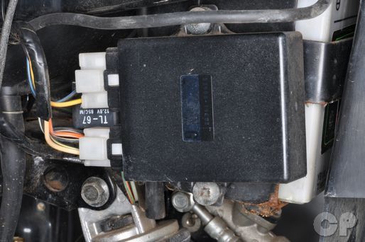
The ignitor box is located on the right side of the sub frame. Remove the connector from the ignition control module.
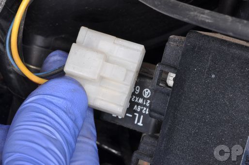
Unplug the larger of the two ignitor box connectors.
Set your multi meter to read ohms of resistance (100 Ω). Check the resistance between the black/blue and yellow wires.
(Pickup Coil Resistance: 135 - 200 Ω)
Ignitor Box
Remove the right side cover to access the ignitor box. See the Side Covers topic for more inforamtion.
Test the ignitor box with the digital ignitor checker.
Special Tool - Digital Ignitor Checker: 09931-64410
Copyright - Cyclepedia Press LLC

Note: If you are viewing this document offline be sure to visit the latest version online at http://www.cyclepedia.com before attempting any repairs. Updates are made without notice.